
The Switchroom
Where does old telephone equipment go to retire? Here's one place. After spending years putting together the best that the Pennsylvania Railroad and the Bell System had to offer (and let's not forget the Independents), it's nice to have an electronic venue where I can show it off. I'll be adding photos from time to time but can't promise something new all the time. I'm having too much fun working on the equipment.
If you are interested in such stuff, you may want to visit the Telephone Collectors International web site.
The photographs are all mine as is the equipment. Some of the photographs also appear on the Tribute to the Telephone site.
I've been dragging this stuff home since the mid 1970's. Assembly started around 1982 and I'm still working on it.
|
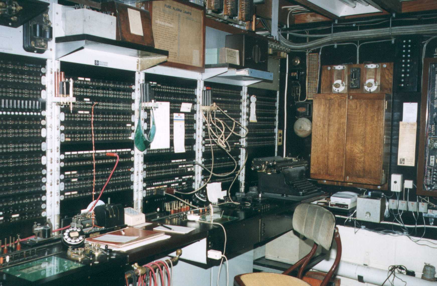
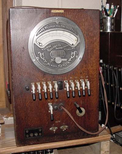
This Western Electric Number 5 Toll Test Board is what started everything. It was assembled from several installations to represent a typical small Pennsylvania Railroad Wire Chief's office. From left to right: The Telegraph Test Board, Blank shelf with selector key, Voltmeter position, Wheatstone bridge and obligatory Underwood Number 5 typewriter. The wooden case on the wall is a 60 type selector ringing apparatus case. There's a lot to see, you can click on the picture for a larger version. |
|
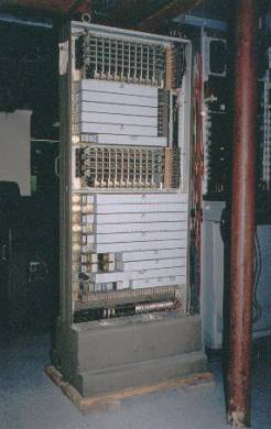
This is an Automatic Electric Type 5 Private Automatic Exchange (PAX). It was built in 1926 and spent most of its "life" in a tannery in Milwaukee, Wisconsin. Although it was originally shipped with connectors only for local service, I installed a shelf of selectors to allow for trunking to other equipment. If you click on the picture, you can see some close-up views of the switch. |
|
|
This is a Western Electric No-Such-Number generator. It's connected to the unused selector levels on the PAX. Click on the image to hear what it does. |
|
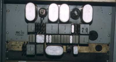
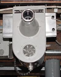
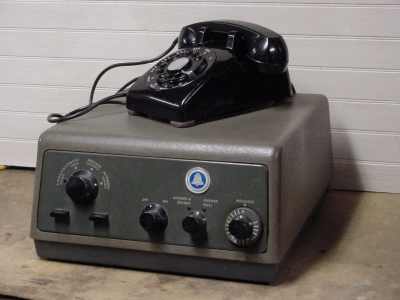
This is a Ringer-Oscillator. It was used to generate and detect a 1000 Hz. tone modulated at 20 Hz. This was used for ringing over composite telephone circuits. A composite circuit is an arrangement of low and high pass filters that allow both telegraph and telephone communications to share a pair of wires. Since 20 Hz. ringing is in the telegraph range, the Ringer-Oscillator allows the use of a voice frequency signal for ringing. Click on the image to hear it. |
|
|
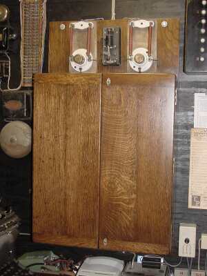
This is a Western Electric 135 Hz composite ringer. It has a similar function to the 1000/20 ringer oscillator above but uses a vibrator generated tone. A tuned reed is used to detect the signal. Click on the image to hear it. Click on the button to see a closeup of the 218B relay. This is what detects the 135 Hz tone. |
|
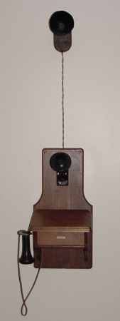
Here's a view of a Western Electric 312 telephone set. It's designed to work on a 135 Hz. composited line. Ringing voltage is supplied by a vibrator that actually uses the induction coil. Click on the phone to see an inside view. |
|
|
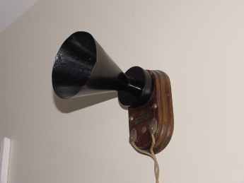
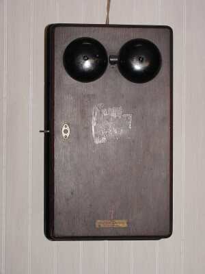
The audible device used with the 312 telephone set is called a howler. It's similar to a watchcase telephone receiver but is adjusted to give a loud buzz when the 135 Hz. ringing voltage is applied. Click on it to hear it. |
|
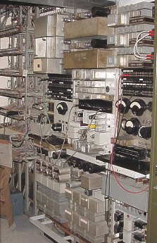
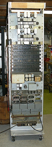
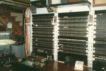
Here is a view of the composite ringing equipment and 22A2 repeaters. The MDF is in the background. The composite filter sets can be seen at the bottom of the last two racks. Click on the picture to see a few closeup views of the equipment. |
|
|
Since any communication circuit needs two ends to be of any use, I built a portable rack to serve as the "west" end of a composited phantom circuit. The test board serves as the "east" end. The rack consists of, from top to bottom, two 1000/20 composite ringers (CXX), the jackfields (Side Circuits LIST*, LINE, DROP, LCX, DCX, LPX, DPX, TL, TD and Phantom Circuit LIST*, PHL, PHD, PCL, PCD), a 135/20 composite ringer (CXX), the power supply for the 1000/20 composite ringers, the phantom coils (COIL) and the composite filters (CX). One of the pairs of coils is actually a novel circuit to derive 120 Hz. from a 60 Hz. source. While not exactly 135 Hz, it's close enough to work with the tuned relay. The two 1000/20 CXX ringers serve the side circuits. The one 135/20 CXX ringer serves the phantom. A separate 24VDC and ringing voltage power supply is also provided on the back of the rack. *LIST or "Listen," not shown on the drawing, bridges the DROP jacks and is used for monitoring the circuit. 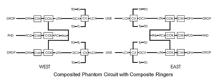
|
|
|
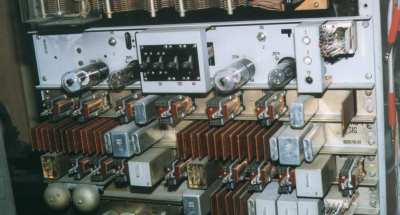
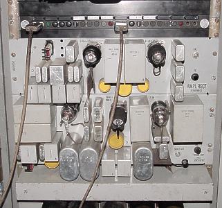
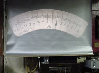
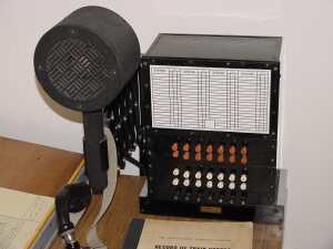
This is a 1U Amplifier Rectifier and a 1W Noise Amplifier Rectifier. These units were used for making transmission measurements in a central office. Connections were made with patch cords to whatever was being tested. The signal level was read off a large display that could be seen from anywhere in the lineup of equipment. Although digital displays were available, the KS-5646 projection meter is certainly more interesting. |
|
|
|
|
This is a closeup of the telegraph test board. The train dispatcher's desk from Philadelphia's 30th. Street Station is in the background. |
|
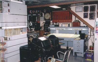
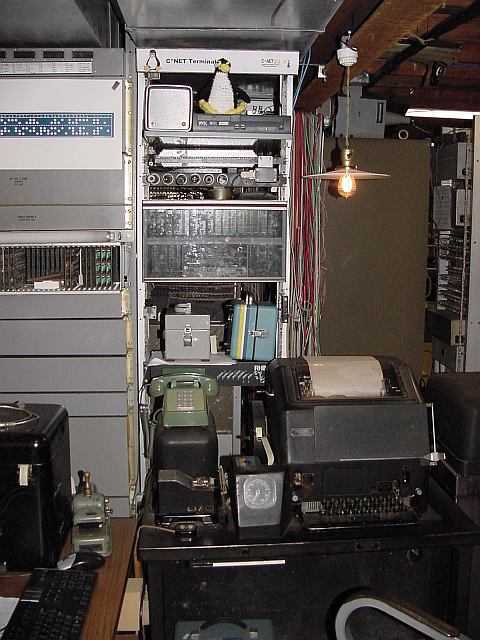
Here is the view of the dispatcher's desk and workbench from behind the testboard. The Model 19 teletype was also from the test board in Philadelphia. To the left is the Automatic Number Identifier (ANI) rack. The ANI unit and the associated Automatic Number Announcer (ANA) is interesting enough to deserve a page of its own. Click on the picture to see more. |
|
|
This is one of the four Train Dispatchers desks from "S" office, 30th. Street Station in Philadelphia. |
|
The Western Electric 60 type selective signaling system provided a means for a train dispatcher to ring one specific tower on a train wire. To ring a tower, a series of 17 polarity reversals is sent out on the train wire. The series is broken into three strings of pulses. The specific number of pulses in each string corresponds to the settings on the selector relay that the series is supposed to ring. Here is a closeup of the 62A key that is mounted on the dispatchers desk. If you click on it, you can hear what the dispatcher would hear when a call is being made. The "sputtering" sound is an answerback signal that indicates that the called station successfully decoded the ring. |
|
|
Here's a 60A selector box. These were mounted in every tower. Click on it to hear it ring. (You will hear two calls. The first one is for this selector and the second is for another.) |
|
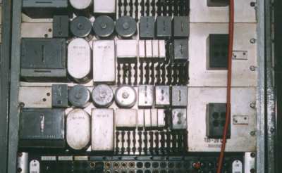
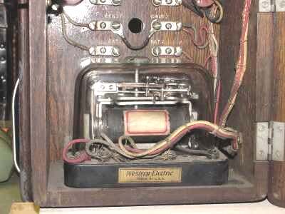
Here's an apparatus case that contains the pole changing relay, line relay and filter network produces the nice rounded thumping sound that's heard when a call is being made. Without this filtering, each polarity reversal would produce an uncomfortably loud pop. Click on the picture to take a look inside. |
|
|
Here's the 60A selector that is the heart of it all. The specific code is set by the location of two pins in the code wheel that can be seen on the upper right of the relay. |
|
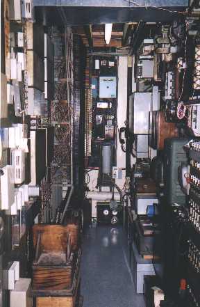
A view behind the repeater and trunk rack. The power supplies, fuse panels, code call, PAX trunk circuits and dial speed tester are on the right. |
|
|
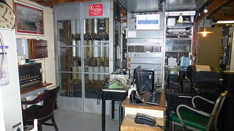
Another view of the AE PAX, ANI equipment and T1 rack. The test console on the far left came from the long gone Sears Eastern Headquarters building on Roosevelt Boulevard in Philadelphia. The wood cabinet between the test console and the PAX is a Western Electric Patch Cord Test Set. |
|
This is a Western Electric 755 crossbar PABX. It's now working and interconnected with the PAX. |
|
|
This is a relatively new rack. It contains the Lynch B325 Channel Bank which handles the analog trunks to and from the PAX. The shelf on top contains a Wyse thin client that hosts the Asterisk soft PBX. The Asterisk PBX serves as the gateway to the Collectors' Network" or C*NET which is a VoIP network that interconnects equipment belonging to worldwide group of telephone hobbyists, collectors, ex-phone phreaks, and other folks who are interested in vintage historic telephone technology. |
|
None of those little, wimpy, plastic answering machines here! This is a 40 pound Western Electric model 1-BA from 1955. Click on the picture to see the inside. (Between you and me, I actually use a newer 27 pound model from the 1970's.) |
|
|
This is a Western Electric type 1407 test cabinet. It came from "PC" office (the wire chief) in the Reading Terminal in Philadelphia, Pennsylvania. (Hmmmm. That means that the wire chief's equipment from two of the three railroads that served Philadelphia are now in the same room. Does anyone know where the B&O one is?) |
|
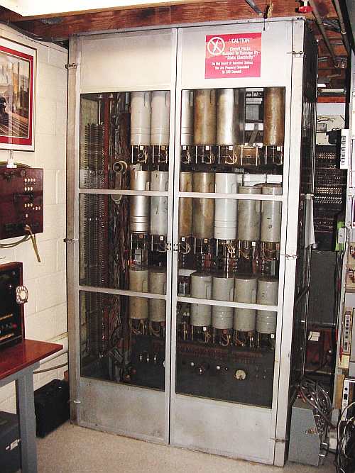
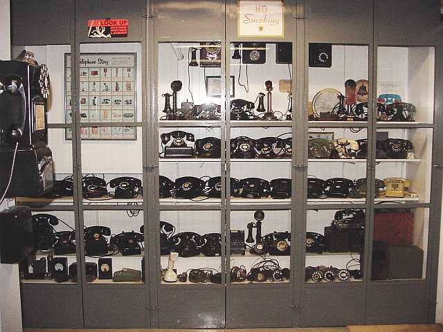
This is the display case done at the end of the switchroom. The doors are off of an Automatic Electric Private Automatic Exchange and are of the same construction as the ones on the No. 5 PAX. |
|
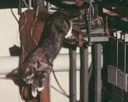
A loose jumper on the frame. |
A Running Jumper. |
Telephone Collectors International
Revised 11/12/20